9.1. 基础分析实验
9.1.1. 实验说明
通过点目标仿真, 分析理解调频率, 分辨率等概念.
Python实现代码, 参见文件 demo_AirboneSAR_Points.py .
实验参数
实验参数如 表 9.1 所示, 类似文献 [1] 中138页的点目标仿真实验中的参数, 部分参数不一致.
参数 |
符号 |
数值 |
单位 |
|---|---|---|---|
平台高度 |
\(H\) |
10 |
\(km\) |
雷达有效速度 |
\(V\) |
150 |
\(m/s\) |
场景中心斜距 |
\(R_c\) |
20 |
\(km\) |
雷达载频 |
\(f_0\) |
5.3 |
\(GHz\) |
发射脉冲时宽 |
\(T_p\) |
2.5 |
\(μs\) |
距离向调频率 |
\(K_r\) |
-20.0e12, +20.0e12 |
\(Hz/s\) |
距离向采样率 |
\(F_{r}\) |
60.0 |
\(MHz\) |
距离向采样点数 |
\(N_{r}\) |
320 |
|
方位向采样率 |
\(F_{a}\) |
100 |
\(Hz\) |
方位向采样点数 |
\(N_{a}\) |
256 |
|
距离向天线孔径 |
\(L_{r}\) |
12.0 |
\(m\) |
方位向天线孔径 |
\(L_{a}\) |
3.0 |
\(m\) |
下视角 |
\(\theta_{d}\) |
30 |
\(°\) |
波束距离向宽度 |
\(\theta_{b}\) |
1.32, 1.32, 1.32 |
\(°\) |
波束斜视角 |
\(\theta_{s}\) |
0.0, 3.5, 21.9 |
\(°\) |
波束中心偏移时间 |
\(\eta_{c}\) |
0.0, -8.1, -49.7 |
\(s\) |
多普勒中心频率 |
\(f_{\eta_c}\) |
0.0, 320, 1975 |
\(Hz\) |
根据上表参数, 可以计算出如下参数
场景中心斜距: \(R_c = H / {\rm sin}\theta_d ≈ 20000.0m\)
最短斜距: \(R_0 = R_c {\rm cos} \theta_s ≈ 18556.7m\)
斜距分辨率: \(\Delta_r = \frac{c}{2B_r} = \frac{c}{2|K_r|T_p} ≈ 2.99m\)
地距分辨率: \(\Delta_x = \Delta_r /{\rm cos}\theta_i ≈ 3.46m\)
方位向距离分辨率: \(\Delta_a=\Delta_y = L_a/2 = 1.5m\)
- 场景中心坐标: \((x_c, y_c)\), \(x_c = {\sqrt{R_0^2 - H^2}}\), \(y_c = R_c{\rm sin}\theta_s\)
\(\theta_s = 0, x_c=17320.50m, y_c=0m\)
\(\theta_s = 3.5, x_c=17286.62m, y_c=1221.45m\)
\(\theta_s = 21.9, x_c=15640.55m, y_c=7462.73m\)
- 近地点斜距: \(R_{near} = H/{\rm sin}(\theta_d+\theta_b/2)\)
\(\theta_s = 0, R_{near}=19609.59m\)
\(\theta_s = 3.5, R_{near}=19610.05m\)
\(\theta_s=21.9, R_{near}=19609.59m\)
- 远地点斜距: \(R_{far} = H/{\rm sin}(\theta_d-\theta_b/2)\)
\(\theta_s = 0, R_{far}=20409.03m\)
\(\theta_s = 3.5, R_{far}=20409.03m\)
\(\theta_s=21.9, R_{far}=20409.03m\)
- 刈幅宽度 (swath size): \(S_x = (H/{\rm tan}(\theta_d-\theta_b/2) - H/{\rm tan}(\theta_d+\theta_b/2)){\rm cos}\theta_s = 921.9{\rm cos}\theta_s\)
\(\theta_s = 0, S_x=923.05m\)
\(\theta_s = 3.5, S_x=921.91m\)
\(\theta_s = 21.9, S_x=880.48m\)
方位向成像宽度: \(S_y = VT_{sa} = 384.0m\)
- 成像区域: \((x_{min}, x_{max}, y_{min}, y_{max})\)
\(\theta_s = 0, SA=(-461.53, 461.53, -192.0, 192.0)\)
\(\theta_s = 3.5, SA=(-460.96, 460.95, -192.0, 192.0)\)
\(\theta_s = 21.9, SA=(-440.58, 439.91, -192.0, 192.0)\)
9.1.2. 调频方向分析
设置目标位于场景中心处, 即相对坐标 \((0, 0)\), 目标强度为 1, 观察不同调频方向, 不同斜视角下的时域(原始信号), 距离多普勒域(原始信号在方位维做FFT), 频域(原始信号在距离和方位上均做FFT)的幅度相位.
零斜视角, \(\theta_s=0.0^°\), 正调频

图 9.1 The property of point target in different domain (positive frequency modulation).
零斜视角, \(\theta_s=0.0^°\), 负调频

图 9.2 The property of point target in different domain (negative frequency modulation).
斜视角 \(\theta_s=3.5^°\) , 正调频

图 9.3 The property of point target in different domain (positive frequency modulation).
斜视角 \(\theta_s=3.5^°\) , 负调频

图 9.4 The property of point target in different domain (negative frequency modulation).
斜视角 \(\theta_s=21.9^°\) , 正调频

图 9.5 The property of point target in different domain (positive frequency modulation).
斜视角 \(\theta_s=21.9^°\) , 负调频

图 9.6 The property of point target in different domain (negative frequency modulation).
9.1.3. 分辨率分析
设置目标为 \((0.0, 0.0), (-6, -6), (-6, 6), (6, -6), (6, 6), (9, 9)\), 目标强度均为1, 进行如下设置.
- 方位向设置
采样率: \(F_{sa} = 100Hz\) 和 \(F_{sa} = 200Hz\)
采样点: \(N_{sa} = 256\) 和 \(N_{sa} = 1024\)
天线孔径: \(L_{a} = 6.0m\), \(L_{a} = 3.0m\) 和 \(L_{a} = 1.5m\)
- 距离向设置
采样率: \(F_{sr} = 60.0e6Hz\)
采样点: \(N_{sr} = 320\) 和 \(N_{sr} = 1280\)
调频率: \(K_{r} = -20.0e12Hz/s\)
脉宽: \(Tp = 2.5e-6s\) 和 \(Tp = 5.0e-6s\)
方位向的分辨率由方位向天线孔径长度与方位向采样率决定, 其中, \(L_a\) 直接决定方位向分辨率上限 \(ΔR_a\), \(F_{sa}\) 决定了能多大程度地恢复方位向分辨率为 \(ΔR_a\) 场景数据. 即使是过采样, 恢复后的最大分辨率仍然为 \(ΔR_a\), 但若是欠采样, 恢复后的分辨率将小于 \(ΔR_a\).
距离向的分辨率由距离向带宽和采样率决定, 其中, \(Br = |K_r|T_P\) 决定了距离向分辨率上限 \(ΔR_r\), \(F_{sr}\) 决定了能多大程度地恢复方位向分辨率为 \(ΔR_a\) 场景数据. 即使是过采样, 恢复后的最大分辨率仍然为 \(ΔR_r\), 但若是欠采样, 恢复后的分辨率将小于 \(ΔR_r\).

图 9.7 Imaging result of RDA.
Imaging result of RDA. \(F_{sa}=100Hz\), \(N_{sa}=256\), \(L_a=6m\), \(F_{sr}=60e6Hz\), \(N_{sr}=320\), \(K_r=10e12Hz/s\), \(T_p=2.5e-6s\)
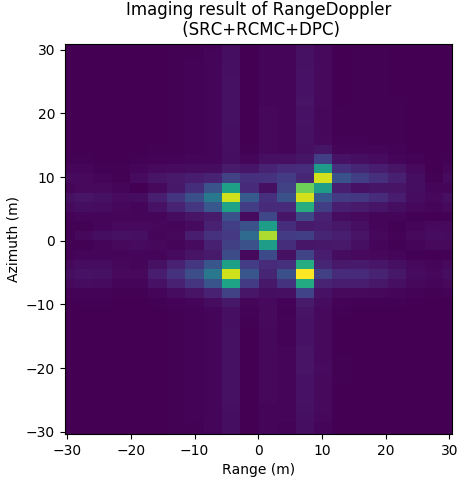
图 9.8 Imaging result of RDA.
Imaging result of RDA. \(F_{sa}=100Hz\), \(N_{sa}=256\), \(L_a=3m\), \(F_{sr}=60e6Hz\), \(N_{sr}=320\), \(K_r=20e12Hz/s\), \(T_p=2.5e-6s\)
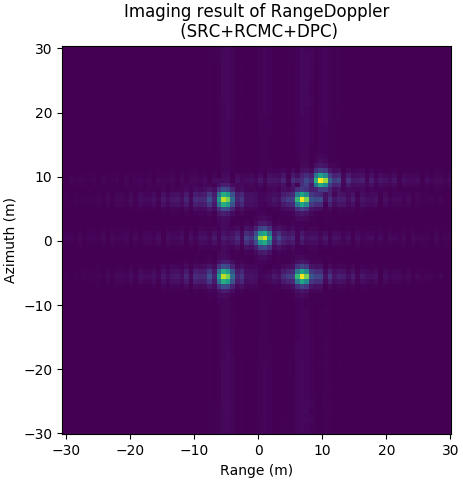
图 9.9 Imaging result of RDA.
Imaging result of RDA. \(F_{sa}=200Hz\), \(N_{sa}=1024\), \(L_a=1.5m\), \(F_{sr}=240e6Hz\), \(N_{sr}=1280\), \(K_r=40e12Hz/s\), \(T_p=25e-6s\)
9.1.4. 距离徙动校正
设置斜视角 \(\theta_s = 8.5^°\), 调频率 \(K_r=20e12, L_a=3.0, L_r=12\), 方位向采样率 \(F_{sa}=100Hz\), 距离向采样率 \(F_{sr}=60MHz\), 目标位置 \((0, 0)\), 目标强度均为1. 分析距离徙动校正的效果, 分析不同大小的 \(\rm{sinc}\) 插值核 \(r=4, 8, 32\) 的影响.
图 9.10 显示的是二次距离压缩及多普勒相位补偿后的结果, 即为进行距离徙动校正, 图 9.11, 图 9.12, 图 9.13 为 \(\rm{sinc}\) 插值核大小分别为 \(r=4, 8, 32\) 的时的距离徙动校正后的结果. 可见, 经过插值核越大, 距离徙动校正越精确.
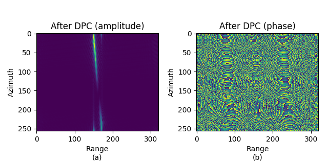
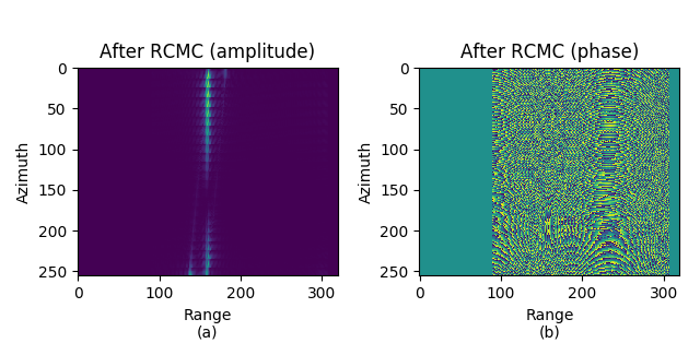
图 9.11 After RC SRC, DPC, RCMC. \(\rm sinc\) interpolation, \(r=4\).
After RC SRC, DPC, RCMC. \(\rm sinc\) interpolation, \(r=4\).
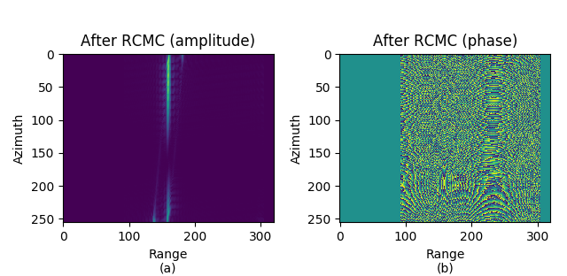
图 9.12 After RC SRC, DPC, RCMC. \(\rm sinc\) interpolation, \(r=8\).
After RC SRC, DPC, RCMC. \(\rm sinc\) interpolation, \(r=8\).
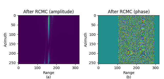
图 9.13 After RC SRC, DPC, RCMC. \(\rm sinc\) interpolation, \(r=32\).
After RC SRC, DPC, RCMC. \(\rm sinc\) interpolation, \(r=32\).
图 9.14 给出了无距离徙动校正条件下, 距离多普勒成像算法的成像结果, 由图可见, 距离徙动现象很明显, 同一目标分布在不同距离与方位单元. 图 9.15, 图 9.16, 图 9.17 为 \({\rm sinc}\) 插值核分别为 \(4,8,32\) 的条件下, 距离多普勒算法的成像结果, 对比 图 9.14 - 图 9.17, 可以发现, 基于 \(\rm sinc\) 插值的距离徙动算法校正效果明显, 且插值核越大, 距离徙动校正越精确.
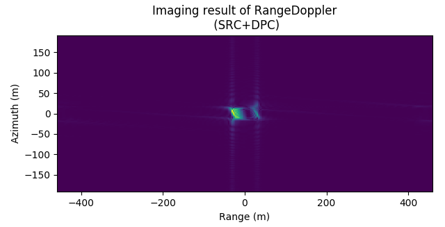
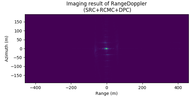
图 9.15 Imaging result of RDA. \(\rm sinc\) interpolation (\(r=4\)).
Imaging result of RDA. \(\rm sinc\) interpolation (\(r=4\)).
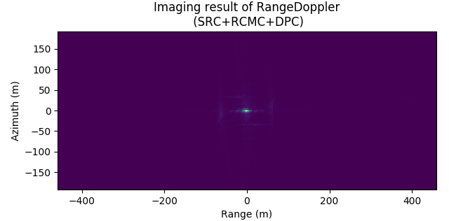
图 9.16 Imaging result of RDA. \(\rm sinc\) interpolation (\(r=8\)).
Imaging result of RDA. \(\rm sinc\) interpolation (\(r=8\)).

图 9.17 Imaging result of RDA. \(\rm sinc\) interpolation (\(r=32\)).
Imaging result of RDA. \(\rm sinc\) interpolation (\(r=32\)).